The Burlington Amateur Radio Club (BARC) has operated repeater stations on Mount Mansfield for many years. The equipment is presently located in the area designated for communications use in a building owned by Vermont Public Television (VPT). This building is located on the south end of the “nose” of the mountain. If you look at the profile of the mountain from a far distance it looks like the side view of a face looking skyward. The “nose” is the high point to the south. The “chin” is to the north. At an elevation of 4393 feet, the chin is the highest point on the mountain and the highest mountain point in Vermont.
In 2003 a joint effort by BARC, NFMRA and W1IMD was undertaken to upgrade the old UHF system (which had been in operation there for several years with newer equipment) and attempt to bring the system up to a good operating condition. Because of the intense radiation (RFI) and inter-mod (IMD) created by all the TV, FM, and other communications transmitters located in the immediate area, making each repeater station work well was not an easy task. But time and patience by W1IMD prevailed and the system now operates very well. The equipment in use at this site is a Motorola MSF-5000 which operates on a frequency of 447.175 / 442.175. CTCSS tones are required to access the repeater; 82.5 Hz for local operation (the link is not keyed up in this mode) and 71.9 Hz was required to link into the MT. Washington system. The MT. Washington link is no longer in use. (See below)
A major consolidation of all the communications equipment on the mountain top took place starting around 2006. All the equipment located elseware on the Mountain, except that belonging to the State of Vermont, was moved to the area where Channel 3 and Channel 33 television facilities had been located for several years. The transition from analog to a digital TV format necessitated making building renovations, removing and replacing transmitters, towers, antennas, etc. This required moving the amateur antennas and equipment as renovations progressed.
In July 2010 the “dust” had almost completely settled. In the Summer of 2009 a Motorola Quindar VHF repeater replaced the old GE Masta II repeater. Both the VHF and MS F-5000 UHF stations were located in the same enclosure. Amateur antenna locations were still not finalized but in a temporary location was agreed upon. Although not the best location, both the VHF and UHF repeaters were back in operation. The UHF repeater no longer connected to the Mt. Washington system but is now linked into the NFMRA system on Killington Peak. The repeater operates in two modes. CTCSS tone of 82.5 Hz is required for local mode. To link into the NFMRA system a CTCSS tone of 110.9 Hz must be used. At this time antenna locations are still not finalized. Coverage from the present antenna locations are relatively good but a better location is still being considered.
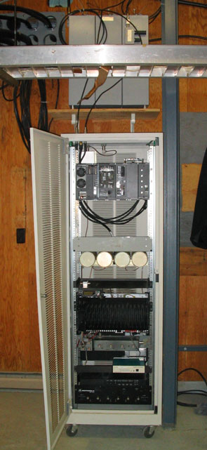
In the photo to the right, located on the shelf behind the cable tray is the duplexer for the two meter repeater. This duplexer, was made by EMR Corp. It is composed of six cavity with dual junction isolators. Followed by:
- Location of the VHF Motorola Quantar repeater.
- UHF Duplexer
- Motorola MSF 5000 UHF power amp.
- Transmitter P A filter.
- Pacific Research repeater controller.
- Motorola MSF 5000 link repeater RF tray and PA.
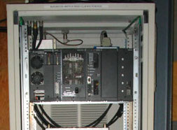
Here is a closer view of the cabinet containing the VHF, UHF and link equipment. The Motorola VHF Quantar repeater is at the top.

This picture shows both of the VHF and HUF repeater antennas.
The VHF repeater (upper) antenna is a Cellwave BA1010 with 0 Db gain .
The UHF repeater antenna (lower) is a DB Products 303 and has 3 Db of gain.
The link antenna was not in place when this picture was taken.
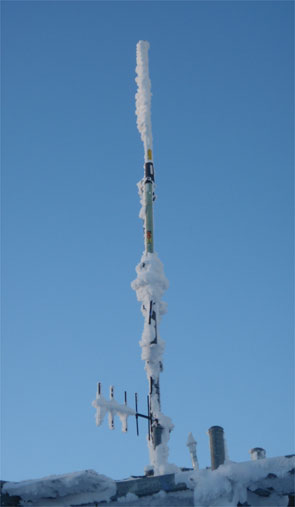
This winter picture will give you an idea of the rime ice that can build up on an antenna. This is mild compared to what it could be. As in the picture above, the top antenna is the VHF repeater antenna.
The UHF antenna is hard to locate as the angle this picture was shot directly in line with the support mast.
The five element link antenna that is a not shown in the above picture is visible here. The make and model are not known.