This site is located in the south central part of Vermont, about six miles east of Rutland. At an elevation of 4,235 feet, it is the highest repeater in Vermont and the second highest in New England, being surpassed only by the repeaters on Mount Washington in New Hampshire. The first VHF repeater system was installed at this site around 1966 and a UHF system followed a few years later. At this site, under the jurisdiction of the State of Vermont, there are presently three amateur repeaters in operation by NFMRA. A VHF repeater operates on 146.280 / 146.880 and the UHF repeater operates on 444.550 / 449.550. Both the VHF and UHF system receivers utilize tone coded squelch circuitry (CTCSS) and the same tone frequency, 110.9 hertz, is used for both systems. The UHF system has always operated with its CTCSS activated. The third repeater is use for the UHF linking system and is referred to as the hub station.
The VHF system operated for may years without CTCSS. It was activated in 2002 because of an increasing amount of transmitter kerchunking (or keying on) caused by onsite RFI garbage and co-channel interference. A VHF system operating at this elevation is capable of providing good coverage out to a radius of 60-70 miles or more, depending on terrain.
A limiting factor affecting coverage from this site is that several other communications systems are co-located here, including two 1-kilowatt FM broadcast transmitters and several two-way radio systems. As additional communications equipment has been added over the years, receiver performance has been degraded due to an increased noise floor as well as periodic intermodulation problems. Severe weather conditions such as high winds, ice, and frost build up on antennas and towers, combined with any loose tower or antenna hardware, contributes significantly to poor receiver performance.
The UHF repeater was installed in the mid 1970’s. Originally, the frequency pair was operated using the low frequency as receive and the high frequency as the transmit. Later, to conform to band plan changes, the frequencies were reversed. Soon after the UHF repeater became operational, a link connection was established from Long Island to the Adirondacks. Killington was used as a relay point. Today the UHF repeater continues to be linked to other sites. This was done in an attempt to provide extended UHF coverage that could be used in emergency situations throughout the area and also to promote usage of the frequencies allocated for FM use in the UHF portion of the band.
Yes, that’s the sound of a frog. Why, may you ask? To introduce some fun into the VHF system back in the early days the recorded sound of a frog croaking was configured so it was transmitted any time the repeater was timed out. When a long-winded person released his push to talk button, the first thing that was heard from the repeater was the frog. Many people got a good chuckle over this feature and it served to remind those who might be a bit long winded about good repeater etiquette. The down side of this was that some would key the repeater on for three minutes just to hear the frog. The frog has been silent for some time now but it may return.
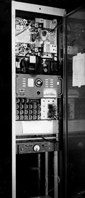
This picture, from the mid-1960s, shows the equipment cabinet containing the first VHF transmitters. Located in the top of the cabinet are two Motorola model 80D transmitters. One of these could transmit on 146.280 or 146.340. A second transmitter could transmit on 146.880 or 146.940. The power supply is located between the two transmitters. Power supply voltages, push to talk, frequency selection, and transmit audio could be switched via the control link to run either transmitter as needed. The “dial box” in the center of the rack did the reprogramming. The relays in the rack below the “dial box” provided the necessary closures needed to switch the various functions. About 25 relays were used. Credit for designing and building this station goes to W1JTB.
Two Motorola Sensicon receivers and the control link receiver were located in a second cabinet. No picture is available as yet. This helped to reduce inter-reaction between transmitters and receivers. The system could be programmed to either operate on 34 in, 94 out or 28 in, 88 out. Or in reverse, 94 in, 34 out or 88 in, 28 out. The system operated on 146.280/146.880 most of the time. The 34 in, 94 out operation could be activated by using a 1Kh tone burst.
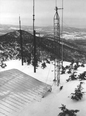
This view of the building and tower, taken around the mid-to-late 1960s, is looking toward the south. The UHF antenna was mounted on the top of the 45G Rohn tower. A 220-509 Phelps Dodge Station Master antenna, used for the VHF repeater, is side-mounted on the tower. The control link antenna was also mounted on this tower.
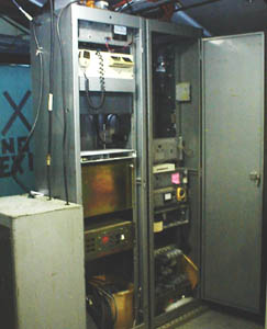
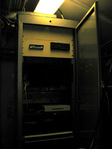
This picture shows the station as it was from about 1994 through 2003. At this point, the equipment has gone through two upgrades since the original system shown above. Notice that the cabinets have remained the same. The UHF station, located in the center of the left cabinet, is a GE Mastr II that runs about 35 watts output from a Celwave model PD 526-4-2 Duplexer. This equipment replaced a Motorola Motrac repeater in 1994. Located at the very top of this cabinet is a RCA TAC 300 UHF station and power supply. This is the link repeater which operates in a hub-type configuration. A Link-Comm RLC-1 repeater/link controller is located in the enclosure seen in the center of the cabinet just above the UHF repeater. The repeater power supply is just under the repeater.
History of the VHF equipment, located in the right hand cabinet, is as follows. A G.E. Mastr Pro station replaced the old original VHF Motorola equipment (shown above) and a Motorola Micor replaced the Mastr Pro in 1998. The Micor station runs 20 watts output from a Sinclair Model F-150 hybrid ring-type duplexer, which is located in the cabinet at the bottom left of the picture. The Sinclair duplexer was replaced with a TX-RX six cavity band pass band reject duplexer.
In late summer of 2003 a fourth upgrade was made to the UHF repeater and linking equipment. W1IMD, who has been a great benefactor to NFMRA, provided two Motorola MSF-5000 stations to replace the GE Mast II repeater and the RCA TAC-300 link unit.

In the picture to the right, which shows just the upper portion of the original cabinet (sill in use) you can see the link duplexer at the very top of the picture. Under the duplexer is the MSF-5000 link repeater. The transmitter PA with the heat fins is next and the receiver and control shelf is at the bottom of the photo. Between the PA and the receiver is the power supply and the PA filter. Transmitter power output of the link is about 30 watts.
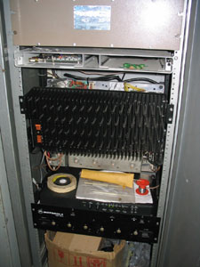
The picture to the right is a continuation of the above picture which shows the bottom section of the UHF cabinet. At the very top of the picture is the duplexer for the main repeater and directly under the duplexer is the Link-Comm repeater link controller. Next is the Motorola MSF-5000 main repeater with its PA, as in the above picture, at the top. Note that this PA is some what larger than the one above as it is capable of producing 100 watts of output power. In this case, transmitter runs about 50 watts.
In 2007 the Link-comm RLC-1 controller was replaced with Link-Comm RLC-4 controller. This change made available two extra link ports. One is used for the Burke Mountain connection and the second port for the VHF repeater.
In the fall of 2008 a Motorola MSF 5000 unit replaced the old Micor. This new(er) repeater in conjunction with the duplexer mentioned above has turned out to be a nice improvement to overall operation of this station. A packet station is shown in the upper part of the rack cabinet.
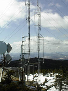
Here is a view of the present towers and antenna configurations. The four-bay antenna mounted on the pipe that extends up from the corner of the building is the UHF repeater antenna. This antenna, made by Shakespear, has been capable of surviving the elements encountered at this site so far. Also located on the same mast are two link antennas. Seen directly above the four-bay antenna is a small omni-directional 2.5 Db gain antenna made by Comtelco, which is used for the hub linking system. The second, a corner reflector, is located just below the four-bay antenna.
Due to weather damage both the link and repeater antennas required replacement in 2008. A Celwave BA6110 replaced the Comtelco and a Telewave 450D6-9 4-bay dipole replaced the old Shakespear.
The VHF antenna, a Cell-Wave 220-509 Super Station Master, is side mounted on the Rohn 45G solid-leg tower seen at the right side of this picture at about the 30-foot level. Because of the angle at which this picture was taken, it is just barely visible alongside the left side of the tower.