The establishment of this site was the result of a combined effort between NFMRA and W1IMD. It was first put on the air in the fall of 2001 by W1IMD. Although this site is actually located in the town of Williamstown, it is referred to as the Graniteville Site because of its close proximity the borough of Graniteville which is located south of the Barre, Vermont.
This site was originally owned and operated by AT&T and was used as a microwave relay station for many years. The site is presently owned by American Tower. The original call sign used at this station was W1AAK. That call was changed to W1JTB which had been the call of a long time club member.
Elevation at this site is 1970 feet AMSL. The antenna support structure is a 238 foot self supporting tower. At this elevation, good UHF coverage is available northwest to Bolton and south to Randolph along Interstate 89. Coverage is also good easterly to East Orange and in some areas in and around Stowe and Hardwick.
During the summer of 2002 the original Motorola MSF-5000 repeater was replaced with a General Electric MASTR II station. Why replace a newer Motorola with an older GE you ask? Well, the Motorola was destined to find a new home at a site to be established in the future. When the MASTR II was installed, a link connection into the NFMRA system on Killington was also put into operation.
The repeater frequencies used here are 444.600 / 449.600 MHz. Two different CTCSS tones can be used to access the repeater depending on user preferences. The system is normally configured so users encoding a 110.9 Hz. tone allows repeater operation plus link access to Killington and into the NFMRA system.
A Link-Comm RLC-1 Plus combined with a RLC-6 are used to interface the main repeater and links both units together. The RLC-1 Plus controller is equipped with a “didga-talker” IC so it will respond verbally to commands that have been entered to it.
A few years ago, the Mount Washington link was discontinued. The RLC-1 Plus controller was replaced with a RLC-1, which uses CW as its ability to talk. However, the station remains connected to the state-wide linked system.

To the right can be seen a typical GE MASTR II station in an upright cabinet. Located at the very top of the cabinet is a DB Products model dB 4076 duplexer. Next, barely visible under the duplexer is the Link-Comm repeater controller panel. Under the controller is the chassis which contains the repeater receiver, transmitter exciter, and power amplifier. A preamplifier is used on the receiver. The transmitter is adjusted to an output power level of about 50 watts. Next in line is the GE station power supply. Located on the right hand side of the rack panel (under the power supply) is the link unit that connects the repeater to Killington. This radio is a UHF GE Phoenix SX mobile unit. The link unit used to connect to Mount Washington is an Alinco DR-235 Mobile unit which operates in the 222 MHz portion of the spectrum. This unit is not visible in this photo. Under the link unit rack is a regulated 13.5 volt power supply that supplies power to both link units and also acts as a redundant supply for the repeater controller. The transmission line to the repeater antenna is 7/8 inch heliax cable and the antenna is a dB Products DB-404.
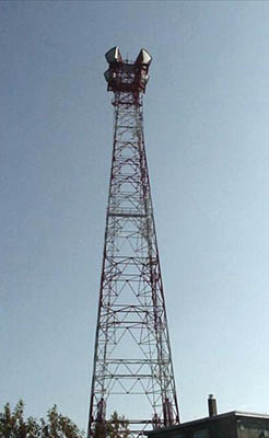
Here we can see almost all of the 238′ tower and the roof of the building as it would be viewed looking in an easterly direction. The (now unused) periscope microwave antennas are still mounted on the very top of the tower. The repeater antenna is barely visible between the two microwave antennas. The microwave antennas shown in this and the next photo have now been removed.
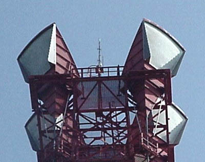
Here is a closer view of the very top of the tower. A better view of the repeater antenna can be seen in this picture. One might now call it a lightning rod instead of an antenna.